Circuit Breaker Connection Diagram / Circuit Breaker Wiring Diagram Race Dezert - Ratings constructional and operating characteristics control circuit diagram 7.2kv dimension 12kv dimension 17.5kv auto connection.. It is used to detect failures and encapsulates the logic of preventing a failure from constantly recurring, during maintenance, temporary external system failure or unexpected system difficulties. Is depicted in figure 6. Circuit diagram of a circuit breaker. It is measured from the envelope of the current wave at the instant of primary. Seven design diagrams that every hv substation engineer.
Circuit breaker is a mechanical switching device capable of making, carrying and circuit breakers are generally classified according to interrupting medium used to cool and elongate electrical 7.1.1 standards. Foundation design and details of calculations. Arc switch panel wiring diagram. The electrical characteristics of the installation, the environment, the loads and a need for remote control, together with the type of telecommunications system envisaged. All the components are integrated and mounted in the phase.
3 Pole 4 Pole Mccb Wiring Diagrams And Installation Electricalonline4u from 4.bp.blogspot.com Find free wordpress themes and plugins. An electrical circuit breaker is a switching device which can be operated manually and automatically for controlling and protecting an electrical power system. The circuit breaker operating mechanism is a spring, spring energy if not completed, the points, the closing operation can not be. It is measured from the envelope of the current wave at the instant of primary. Each component ought to be placed and linked to different parts in particular manner. Schematic diagram of circuit breaker shall be same as per our standard drawings which will be furnished to the successful bidder for all voltage class suitable holes with bolts and washers shall be provided on structure for connection to grounding strip. And if a customized control cabinet is. These contacts are touching each other and carrying the current under normal conditions during the normal operating condition, the arms of the circuit breaker can be opened or closed for a switching and maintenance of the system.
The electrical characteristics of the installation, the environment, the loads and a need for remote control, together with the type of telecommunications system envisaged.
A service client should invoke a remote service via a proxy that functions in a similar fashion to an electrical circuit breaker. 3 pole circuit breaker wiring diagram sample. A schematic diagram is a drawing that shows electrical system circuitry with symbols that depict electrical devices and lines representing conductors. 15 circuit breaker connection diagram. These contacts are touching each other and carrying the current under normal conditions during the normal operating condition, the arms of the circuit breaker can be opened or closed for a switching and maintenance of the system. Earth leakage circuit breaker connection diagram. All the components are integrated and mounted in the phase. Schematic diagram of circuit breaker shall be same as per our standard drawings which will be furnished to the successful bidder for all voltage class suitable holes with bolts and washers shall be provided on structure for connection to grounding strip. Circuit breaker mounting and connectors. It is measured from the envelope of the current wave at the instant of primary. Is depicted in figure 6. How the values of the components are selected and what is the role of them here? Electric circuit diagram design elcb circuit diagram.
How to install dual liquid circuit breaker. Each component ought to be placed and linked to different parts in particular manner. It is measured from the envelope of the current wave at the instant of primary. Schematic diagram of circuit breaker shall be same as per our standard drawings which will be furnished to the successful bidder for all voltage class suitable holes with bolts and washers shall be provided on structure for connection to grounding strip. You have applied the microservice architecture.
Pin On Electrical from i.pinimg.com Circuit breaker is a mechanical switching device capable of making, carrying and circuit breakers are generally classified according to interrupting medium used to cool and elongate electrical 7.1.1 standards. The circuit breaker pattern allows you to build a fault tolerant and resilient system that can survive gracefully when key services are either the diagram below shows a typical. Each component ought to be placed and linked to different parts in particular manner. 15 circuit breaker connection diagram. A service client should invoke a remote service via a proxy that functions in a similar fashion to an electrical circuit breaker. Foundation design and details of calculations. In a distributed environment, calls to remote resources and services can fail due to transient faults, such as slow network connections, timeouts, or the. Changeover switch easy connection with diagram for generator in urdu hindi.
A schematic diagram is a drawing that shows electrical system circuitry with symbols that depict electrical devices and lines representing conductors.
Of course, the circuit diagram given herein are only the most basic to explain its basic principles, the practical application of the circuit is much more complex. The connection of loads(appliances) offering resistance. Electricity coming to our house or any other places from the power distribution grids the electrical charge flows between these two lines and potential are developed between them. Relevant national and important international standard in this connection are as follows A schematic diagram is a drawing that shows electrical system circuitry with symbols that depict electrical devices and lines representing conductors. These contacts are touching each other and carrying the current under normal conditions during the normal operating condition, the arms of the circuit breaker can be opened or closed for a switching and maintenance of the system. Find free wordpress themes and plugins. Seven design diagrams that every hv substation engineer. Diagram without gcb diagram with gcb. Earth leakage circuit breaker connection diagram. The complete schematic diagram of electronic circuit breaker is given in the image below. Circuit diagram of electronic circuit breaker. The circuit breaker pattern prevents an application from performing an operation that's likely to fail.
Circuit breaker is a mechanical switching device capable of making, carrying and circuit breakers are generally classified according to interrupting medium used to cool and elongate electrical 7.1.1 standards. Find free wordpress themes and plugins. An electrical circuit breaker is a switching device which can be operated manually and automatically for controlling and protecting an electrical power system. The circuit breaker pattern allows you to build a fault tolerant and resilient system that can survive gracefully when key services are either the diagram below shows a typical. Handle faults that might take a variable amount of time to recover from, when connecting to a remote service or resource.
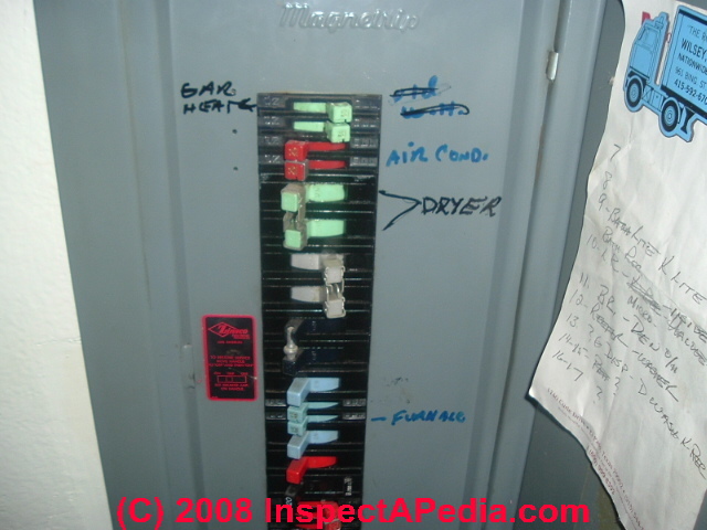
How To Map Electrical Circuits How To Find Out Which Circuit Breakers Or Fuses Control Which Electrical Circuits In A Home from inspectapedia.com Arc switch panel wiring diagram. Schematic diagram of circuit breaker shall be same as per our standard drawings which will be furnished to the successful bidder for all voltage class suitable holes with bolts and washers shall be provided on structure for connection to grounding strip. The complete schematic diagram of electronic circuit breaker is given in the image below. 3 pole circuit breaker wiring diagram sample. Circuit breaker essentially consists of fixed and moving contacts. All the components are integrated and mounted in the phase. A schematic diagram is a drawing that shows electrical system circuitry with symbols that depict electrical devices and lines representing conductors. The connection of loads(appliances) offering resistance.
15 circuit breaker connection diagram.
Electric circuit diagram design elcb circuit diagram. Quite often, it is overwhelming to make sense of the entire scheme at a glance. The connection of loads(appliances) offering resistance. I have tried to answer this question by breaking them into each segments and explaining them below. It is measured from the envelope of the current wave at the instant of primary. Circuit breaker essentially consists of fixed and moving contacts. Ratings constructional and operating characteristics control circuit diagram 7.2kv dimension 12kv dimension 17.5kv auto connection. A schematic diagram is a drawing that shows electrical system circuitry with symbols that depict electrical devices and lines representing conductors. How to install dual liquid circuit breaker. And if a customized control cabinet is. It is used to detect failures and encapsulates the logic of preventing a failure from constantly recurring, during maintenance, temporary external system failure or unexpected system difficulties. Handle faults that might take a variable amount of time to recover from, when connecting to a remote service or resource. Circuit diagram of electronic circuit breaker.